Rolling Resistance

Jacer Race CarsHave you ever put 30lbs in your Vee tyres and noticed how easy it has suddenly become to push? In short, it’s rolling resistance. The contact patch of the tyre to the ground has shrunk in relation to your normal pressures, giving you less resistance or effort required to move the vehicle.

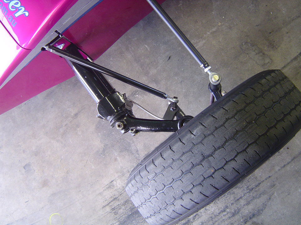
It may be impractical to use 30lb pressure in your tyres in a racing situation as that lack of contact patch to the track becomes a disadvantage, but other parts of the car can give you a similar resultant gain. The most basic of resistance in our cars come through the brakes. Be it either drums or discs, the result is the same.

If when you jack your drum brake car up you can?t rotate the wheel and have it spin easily for at least 7 to 10 seconds (front wheel here) there is a resistance that the engine must overcome. Wheel bearing and brake adjustment will be your main area of gain there. Disc brake cars are slightly different though. Yes, wheel bearing pre loads are something that are important, but brake adjustment is non-existent, so is there anything that can be done to help?

Yes, of course! By nature of the system, the pedal doesn’t move that far, meaning that the caliper and master cylinder also don’t move that far, and unlike a drum brake set up, discs don’t generally have a proper return spring to retract the pads away from the discs. In time they can stick slightly, meaning the release of the pad from the caliper becomes a lot slower.

Something simple that you can do yourself is to remove the wheels and push the pads back slightly and then pump the pedal until the pads are pushed back out again against the discs. Do this a few times on all wheels and you should find the pad „releasing? a lot faster. If you have the VW callipers and the anti rattle springs have been removed, put them back in. They act as a form of return spring also. It goes without saying that the gearbox consumes its fair share of h.p. through its resistance.

Internal pre loads and viscosity of lubricants play their part. The same can be said for the engine with piston ring drag or valve train friction, but if you don’t have the budget to chase drive train frictional losses, there are gains to be had in the most basic of areas with just a little bit of time and effort.

Wheel Alignment

Formula Vee Wheel AlignmentHi, this time I’ll cover a basic Formula Vee wheel alignment. This will use the string method which is the only practical method you can use at a race track.

Firstly you need to get something that you can tie string to that has a height roughly at the axle height of the car. Two bars with pins the same distance apart set up on car stands will do. The idea here is to set two parallel strings either side of the car and have the car set up with its centerline parallel to the strings. When you measure from the string to the car you won’t have the same measurement front to rear, but side to side will be – the measurement from the front axle to the string may be 100mm but the rear may be 90mm.

Providing that the string in front of and behind the car is the same distance apart, and both sides at the front axle are the same and both sides at the rear axle are the same, then the car should be parallel inside the „box”. Depending on the type of rear suspension you have, you?ll need fairly flat ground, but not spirit level flat. For a twin coil over or rear torsion car, you will, but that’s not going to be covered here. Once you’ve got your car straight inside its “box”, you?ll need to set the steering wheel straight ahead and come up with a method to hold it there.

It must be noted that if you are going to adjust camber/caster, you have to do this first. Any time you change camber/ caster (the eccentric not under the top ball joint will do both) on a ball joint front end, toe will change. Measure out from the string to the front of the tyre, and then from the rear of the front tyre to the string. If those measurements are 95 mm at the front and 100 mm at the rear on the left hand side, for example, then that side has 5 mm toe out.

Repeat the same for the remaining three corners and adjust according to the settings required. Noted again that I will measure off the tyre, NOT the rim. The rim?s straightness will depend on how many curbs it has hit, and some of the rims I see look like the car has been dropped off a building (sorry guys!). Small deviations in the rim will affect your alignment. However, the tyre will tend to even itself out better than the rim. This is just a basic reference as to the method of checking toe in/toe out. What you set things to will depend on the manufacturers settings.

Grab the spanners and have a go.

Valve Clearance

Jacer Rocker Valves Formula VeeI’ve been asked to write something about valve lift. It?s a pretty topical subject amongst a few people I?ve spoken to. I?ll try to cover the rule as it is now and how we got there rather than the how to’s.

From my memory it was the early nineties that the practice of removing metal from the area around the underside of the rocker where it fouls on the valve spring retainer first was noticed. Occasionally before this you might find people lightly clearancing one or two rockers out of a set when the rocker would foul on the retainer or just shim the rocker posts out (which was the legal way). The advent of grinding the rockers for advantage was a step further away from legal.

It was determined that this process was “balancing”. Once the precedent was set open slather became the norm for the next 20 years. We move on to the later 2000?s and lengthening of pushrods up to around 8mm longer than std, grinding the 1600 rockers through to the oil feed holes to be able to stand the rocker screw somewhere around parallel to the rocker post stud was becoming the norm.

Machining of the rocker posts to stop the screw from falling off the edge of the valve end during its lift cycle all combined with excess wear in the valve train. Rockers would break from being so weak around the ground section. Pushrods would break from binding in the pushrod end of the rocker from over centering.

Valve guides would wear from the harsh angles and lack of valve rotation. People were machining up their own offset rocker studs to try to lower the rocker gear to help with some of these dramas.Towards the end of 2007, the best I think I saw on our car was around 10.8mm lift on the inlets, and 10.2 on the exhausts.

Some I believe would be getting quite more from 1.25:1 rockers and the use of lash caps both of which were generally considered not to be legal in 2007. To get 10.8mm though meant you needed to make up a jig to measure rockers looking for the machining variations through production. I can remember in late 2006 checking a 100 ltr container of rockers for 3 sets of „good ones?.

It took roughly 5 hrs to do but gains were there to be had. We move on to now with fixed valve lift which was introduced to help reliability and „parity?. I?m not going to go into the how?s etc with the new system other than to say that the lift isn?t a consistent figure and will change with wear and heat. If you replace a tappet screw it will have an effect on lift. If you break a pushrod and the one you replace it with isn?t the same length the lift will change.

If you pull a head off and change a valve unless the end of the valve is the same length as the one you replace lift will change. If you do a top end and re-cut the valve seats lift will change. I believe that moves are heading towards a 1.25:1 rocker being introduced which will make it easier to get lift required but may not be the perfect ideal.

As with most things progress over the next couple of years will determine the next set of problems for the tech guys to argue over.

Dynotuning

Jacer DynoHi again for one last time in 2010. I’ve been asked to write a little about dynos. Hopefully it may be of some interest. I feel the need to make a couple of points first before getting into this.

First, in my opinion, a dyno is a handy and helpful tool, but don’t consider it to as the be all and end all to your on track performance.

Secondly, not only do all dynos read slightly differently, but you will get different reading depending on the method the operator uses.

Thirdly, having your car tuned and making a million horsepower at 9 o’clock at night doesn’t mean you will have a million horsepower at midday the next day.

Finally, a dyno should be used for back to back testing of components and tuning, and that before you get there the basics should have been checked. The intention of the final point in the previous paragraph is meant to indicate that unless you are trying to find an oil leak or source a dodgy wiring problem, then it is wise to make sure the car has all the basics covered. At anywhere from $150 to $200 per hour having a flat battery, running out of fuel, or having the engine dump the contents of it’s sump on the floor, isn’t money well spent.

On the subject of fuel, it is wise to make sure your car is dyno’d with the fuel you normally run. On an initial run for a carb, you may find you will have to change float levels at the race track after your trip to the dyno to deal with cornering flat spots. This will affect you mixtures to an extent.

Points one and two of the previous statement relates to the weather, or more specifically, air density. Most of the front guys, when they dyno their car, tend to have at least an air density gauge with them. Some guys will run their own lambda sensors in the exhaust. Peak hp readings will be taken after final jetting/tuning. Lambda (or CO) readings along with the air density readings will also be taken down.

At the racetrack, as the air density changes, calculations will be made to the jetted carb depending on what you have weather-wise on the given day. Sometimes these changes may be in the region of .025mm to .05mm. That sort of sums up the first three statements in that the h.p readings given are only a snapshot of the conditions of that time, but can be of great value at the racetrack if used correctly. I could spend time talking about jetting the pilot circuit, the main circuit, the air correction circuit, or why cars foul plugs in the pit or at Wakefield.

I could go on about what a difficult carb we run, and how the restrictor plate leans off mixtures on throttle opening leading to the reason of fouling plugs.

But I may leave that for another time. See you at the track.

Coca Cola Series At Amaroo Park

Footage from Amaroo Park 1987…enjoy!

CHASSIS F2K10-61

SERIES
JACER F2K10
DATE BUILT
2010
CHASSIS #
F2K10-61
OWNER(S)
MAT PEARCE/ BRUCE PEARCE APR 2010

NA

CHASSIS F2K10-60

SERIES
JACER F2K10
DATE BUILT
2010
CHASSIS #
F2K10-60
OWNER(S)
NA

NA

CHASSIS F2K10-59

SERIES
JACER F2K10
DATE BUILT
January 2010
CHASSIS #
F2K10-59
OWNER(S)
RICHARD NAIRN
SIMON DUFFY

Notes: Turnkey car for Nairn

CHASSIS F2K9-58

SERIES
JACER F2K9
DATE BUILT
2009
CHASSIS #
F2K9-58
OWNER(S)
NA

NA

CHASSIS F2K9-57

SERIES
JACER F2K9
DATE BUILT
February 2009
CHASSIS #
F2K9-57
OWNER(S)
NA

NA